Hydraulic Tank Reservoirs
HYDRAULIC RESERVOIRS
PURPOSE
Reservoirs serve three purposes in the hydraulic system:
- They store the oil until the system requires it.
- They help provide for the cooling of the oil.
- They provide a place for contaminates to “settle out” of the oil.
When selcting a tank reservoir, style/shape, material, capacity, placement, venting and porting are important considerations.
CONSTRUCTION
Oil reservoirs can be constructed from steel, stainless steel, aluminum or polyethylene plastic. Each of these materials has benefits and drawbacks which should be considered when selecting a reservoir.
STEEL

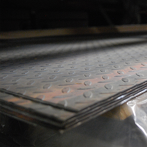
Steel reservoirs are good dissipaters of heat and are relatively easy to construct. Steel plate is readily available and inexpensive. However, steel reservoirs are susceptible to moisture condensation and rust. Also, it is not uncommon to find welding slag and splatter, which can damage system components inside steel reservoirs. Steel is also heavy.
STAINLESS STEEL


Stainless steel is much more resistant to corrosion in comparison to mild steel and is also a good dissipater of heat. Stainless steel is very durable and offers a relatively high resistance against rough materials. Reservoirs manufactured from stainless are more expensive but remain a popular choice for their appearance and durability.
ALUMINUM
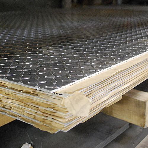
 Aluminum is both an attractive material and an excellent dissipater of heat, providing three times the heat transfer rate of steel. It is the choice of owner operators who equip their trucks with custom paint jobs and every imaginable option. But aluminum is expensive and requires a higher level of skill on the part of the fabricator. Aluminum is a fragile material that will fatigue crack due to excessive weight on the fittings or prolonged expansion and contraction of the material. Increased air exchange, clean breathers and well supported hoses are prudent in aluminum tank application. Also, condensation can cause aluminum to oxidize.
POLYETHYLENE

Polyethylene plastic “poly” reservoirs are light in weight and can be molded in various shapes and even colors. The manufacturing process does not generate contamination particles and poly is less susceptible to moisture condensation. However, polyethylene is not a good dissipater of heat and should not be used for long duty cycle applications like hydraulic motor drives or live floors. Use it instead for dump, roll-off or ejector type applications which have short duty cycles.
CAPACITY
How large does a reservoir need to be to ensure an adequate supply of oil? There are two rules of thumb that can be used as a starting point. If the hydraulic system uses cylinders as its actuators, the reservoir capacity should equal the volume of oil required to extend the cylinders plus 20% (or four to six inches) reserve in the tank. If the system utilizes hydraulic motors as actuators, the reserve capacity should equal twice the operating system flow rate. These rules are not absolute; they are affected by such factors as ambient temperature, length of duty cycle, frequency of use, etc. Remember, the goal is to keep an adequate supply of oil and to keep it cool.
PLACEMENT
Placement of the reservoir is important. The primary job of the reservoir is to provide oil to the pump. Therefore, the ideal location is close to and directly above the pump’s inlet port. While possible in an industrial setting, this is often impossible to achieve in a truck mounted system. When the pump is mounted on the front of the vehicle or on top of the engine, the reservoir outlet is likely to be several feet away and below the pump inlet. In these conditions it is important that the inlet hose be oversized and kept as straight as possible to prevent cavitation of the pump. In some cases, it may be necessary to use a sealed, pressurized reservoir.
CONSTRUCTION CONSIDERATIONS

The reservoir must be able to breathe (to take in and exhaust air) as the fluid level changes. Therefore, it is important that the reservoir be equipped with a vent or breather cap. An improperly vented reservoir can starve the pump and possibly damage the reservoir, so clean the breather frequently.

The reservoir should be constructed so that returning oil flow always enters the tank below the oil level, either by placing the return port at the bottom or by directing the oil through a stand pipe to the bottom. Oil entering above the fluid level may create foam and air bubbles (aeration), which can then enter the system resulting in sluggish or jerky operation. A diffuser will further dissipate oil flow below the fluid level. Diffusers effectively manage high volume return flows common with dump applications.
PORTING

Another important design consideration is tank port placement and size. The pump inlet and return ports should be on opposite ends of the reservoir to allow the returning oil to lose heat before again being drawn into the system.

To further keep the warmer, returning oil away from the pump inlet port and to help prevent sloshing, tanks may be equipped with baffles. Baffles should be located so as to direct the returning oil toward the walls of the reservoir where heat can be transferred to the atmosphere. The oil should take the longest possible route to the tank’s outlet port. To keep settled contaminates from entering the system, the tank outlet port should be raised slightly from the reservoir bottom.
OTHER OPTIONS
Low profile tanks may be attractive from the standpoint of ground clearance, but they can expose the pump inlet to atmosphere when operating off-road or on an incline. In addition, pump vacuum may create a vortex and draw air into the system. Temperature and fluid level gauges, fill screens, clean-out ports and magnetic drain plugs are useful options for hydraulic oil reservoirs.

Return line & suction line filters are also a very important part of the hydraulic system. Contaminants in the hydraulic system can be very damaging and even catastrophic to the entire system. Changing filters on a regular basis keeps your system and oil clean and less susceptible to failure.
To improve inlet conditions in piston pump systems, pressurized reservoirs are frequently used. Three to four psi is normal for these applications.
CALCULATING RESERVOIR CAPACITY
Calculating reservoir capacity is a matter of simple geometry. For square or rectangular tanks multiply the length (in inches) by the height, by the width. This will yield the volume in cubic inches. Convert it to gallons by dividing by 231.
For cylindrical reservoirs we use the same formula that we used to determine the fill volume of a hydraulic cylinder, 3.14 x r² x L / 231 equals gallons.
NOTE: The above example does not consider the reservoir wall thickness, which will take away slightly from the actual capacity; along with the air gap; baffles or support structure; port size and location; or minimum oil level above the port to prevent uncovering or a vortex affect. Subsequently, the usable capacity of a reservoir is considered to be 80% of its total calculated volume.
Disclaimer: All the above comments are for informational purposes only. At no point is this page to be used for instructional purposes. Each hydraulic system has specific needs. The above is purely basic knowledge or principles to help you build your system.